
Yuuhseel 2‑Pack A4950 Dual‑Channel DC Brushed Motor Driver Board, Pre‑Soldered Pins, Compatible with Arduino, Raspberry Pi, ESP32


Yuuhseel 2‑Pack A4950 Dual‑Channel DC Brushed Motor Driver Board, Pre‑Soldered Pins, Compatible with Arduino, Raspberry Pi, ESP32
Key features
- This A4950 dual‑channel driver module works within 7.6V‑30V input voltage and supplies 2‑amp continuous current for each channel.Recommended PWM Frequency:500Hz~30kHz.
- It can control forward‑reverse rotation of two independent DC motors. Only one single module is enough for self‑balancing robot car projects.
- Control Requirements: Four PWM pins are needed to realize both forward and reverse‑rotation functions. Only two PWM pins are required if reverse‑rotation function is not needed.
- This module is equipped with 2‑A current‑limiting protection. Instead of shutting down under over‑current conditions, it only caps the maximum output current.
- Module Pin‑out Description: VM: Power‑supply pin for the driver module. Input voltage should match your motor specifications with a practical working range from 7.6V‑30V VCC: 5‑V power‑supply input. 3.3V input is not recommended; otherwise module performance will be compromised. GND: Ground pin.
Parameter Working Voltage:7.6V~30V Typical Max Current:2A(2‑Way Motor Output) Recommended PWM Frequency:500Hz~30KHz Size:23*18*11mm Weight:3g Module Pin‑out Description: VM: Power‑supply pin for the driver module. Input voltage should match your motor specifications with a practical working range from 7.6V‑30V. VCC: 5‑V power‑supply input. 3.3V input is not recommended; otherwise module performance will be compromised. GND: Ground pin. Control Examples (After the above‑mentioned 3 pins are properly wired): Task 1: Motor A runs forward with 50% PWM duty cycle. Solution: Connect two wires of Motor‑A to AOUT1 and AOUT2 respectively. Set AIN1 to low logic level and apply a 50%‑duty‑cycle PWM signal to AIN2. Task 2: Motor B runs in reverse with 20% PWM duty cycle. Solution: Connect two wires of Motor‑B to BOUT1 and BOUT2 respectively. Set BIN1 to high logic level and apply a 20%‑duty‑cycle PWM signal to BIN2. (If your PWM frequency is relatively high such as 10kHz, two PWM pins are required to control forward and reverse rotation. Arduino’s default PWM frequency is 500Hz; under this condition you can control rotation direction with one regular I/O pin plus a single PWM pin, yet the perf
Free shipping included. 30-day hassle-free returns.
More in AC Electric Motors
1517 products · See all AC Electric Motors →

 DC31-20014C Washer Clutch Motor for Samsung Drain Shift Actuator Shifter
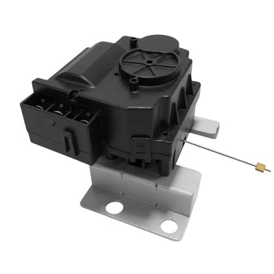 New DC31-00203A Washer DC Motor Clutch Compatible with Samsung Washing Machine,Replacement for DC31-00203A Washer Motor Clutch Assembly

 Noteflora 12V DC Brushless Motor 130000 RPM Aluminum Alloy Impeller and Copper Coil for Handheld Dust Blowers and High-Speed Turbo Fans(12V 13W+Plate)
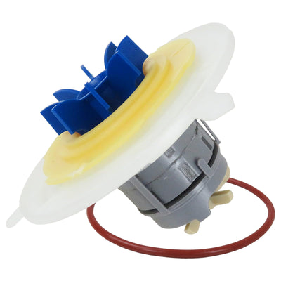 Suifaqi 524285P, 528136P Motor Rotor Assembly Dishwasher Drawer Pump Replaces 1636354, 524285, 528136, Compatible with DD605 DS605 DD60S DD60D DD24S DD24D DD224 DDSDF Models (2026 NEW)
 Whirlpool W10890624 Genuine OEM Top Load Washer Motor Drive Assembly Replacement Part - Replaces W10623547
